Fan Installation
Overview
Fan Thickness Compatibility
Only Fan Wall 1 and Fan wall 3 are capable of 35mm thickness fans. Fan Wall 2 is only able to fit 25mm thickness fans.
Fan Wall Compatibility
All fan walls use 120mm fans.
Hako-Core
- Hako-Core supports up to 3 fan walls totaling 9 fans total (120mm)
- 1 Exhaust fan (80mm or 92mm)
- Auxiliary fans for PCIe cooling
Hako-Core Mini
- Hako-Core Mini supports up to 2 fan walls totaling 6 fans total (120mm)
- 1 Exhaust fan (80mm or 92mm)
- Auxiliary fans for PCIe cooling
Auxiliary fans can be mounted using one of our fan brackets:
For the fans themselves, we recommend the Noctua NF-F12 industrialPPC-3000 PWM.
Installation Process
Safety First
It is always recommended to power down the system when working inside the case.
Fan Wall 1
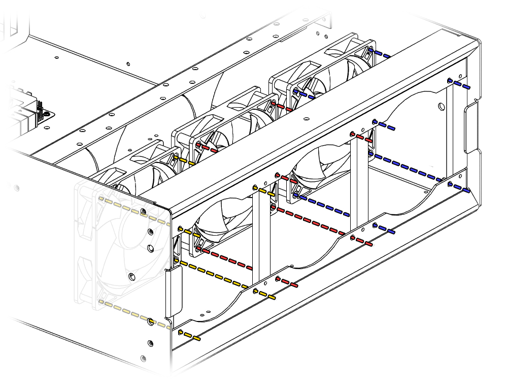 Remove the magnetic faceplate and install the fans using the mounting holes.
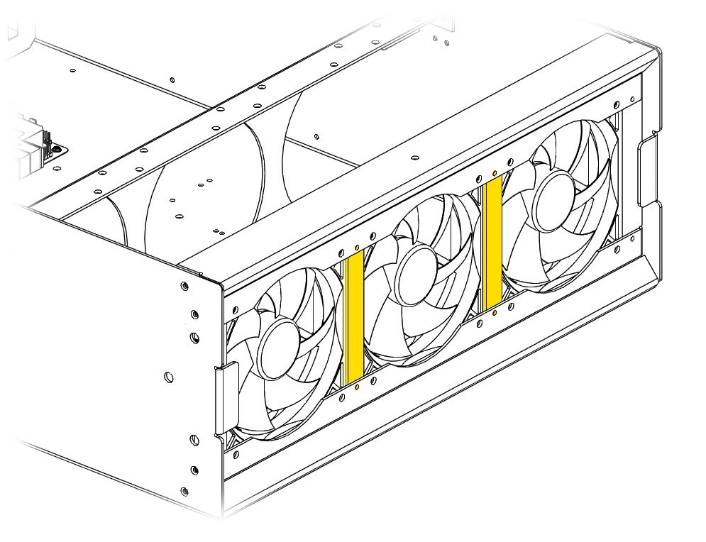
Air Block Clearance
The 3D printed air blocks may be too tight for fan installation. Unscrew these and reinstall them along with the fan at the same time to get them to fit together.
Fan Headers
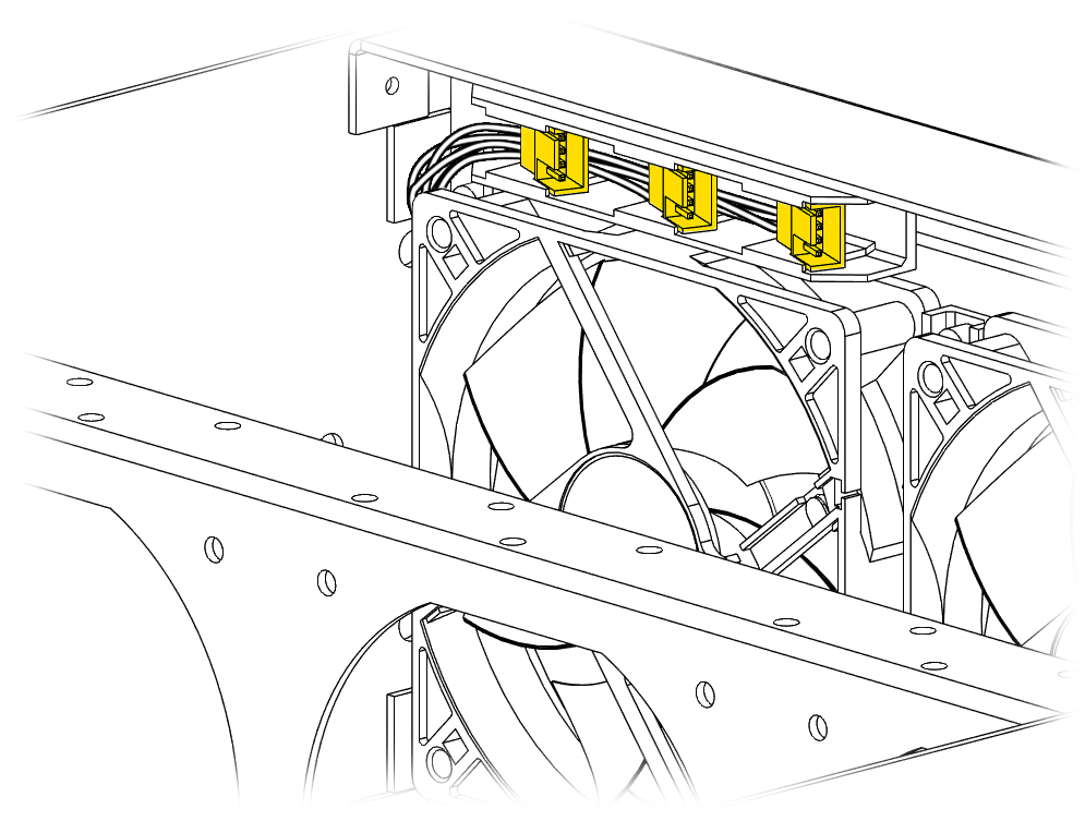 The fan headers for Fan Wall 1 are located above the the left fan and connect to the powerboard. Plug the fans in here and tuck the wires in between the fans.
Fan Wall 2/3
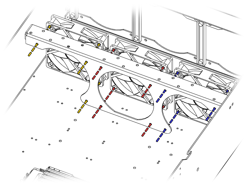
Middle Fan Headers
Fan Wall 2 uses fan extension cable to connect to the powerboard. Plugging the fans in first and tucking the wires under the fan makes the install easier.
Install the fans using the mounting holes. Fan wall 2 and 3 use similar mounting points. The fourth screw on the edge fans are not used.
Fan Extension
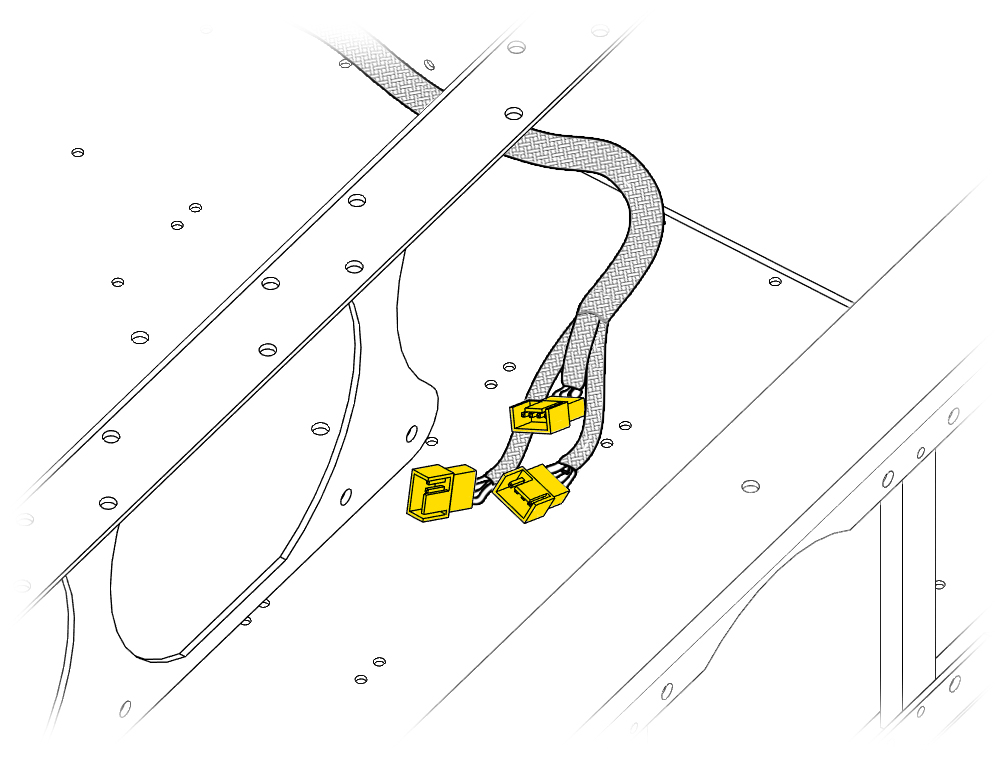 This cable is used for Fan Wall 2.
Exposed Powerboard Headers
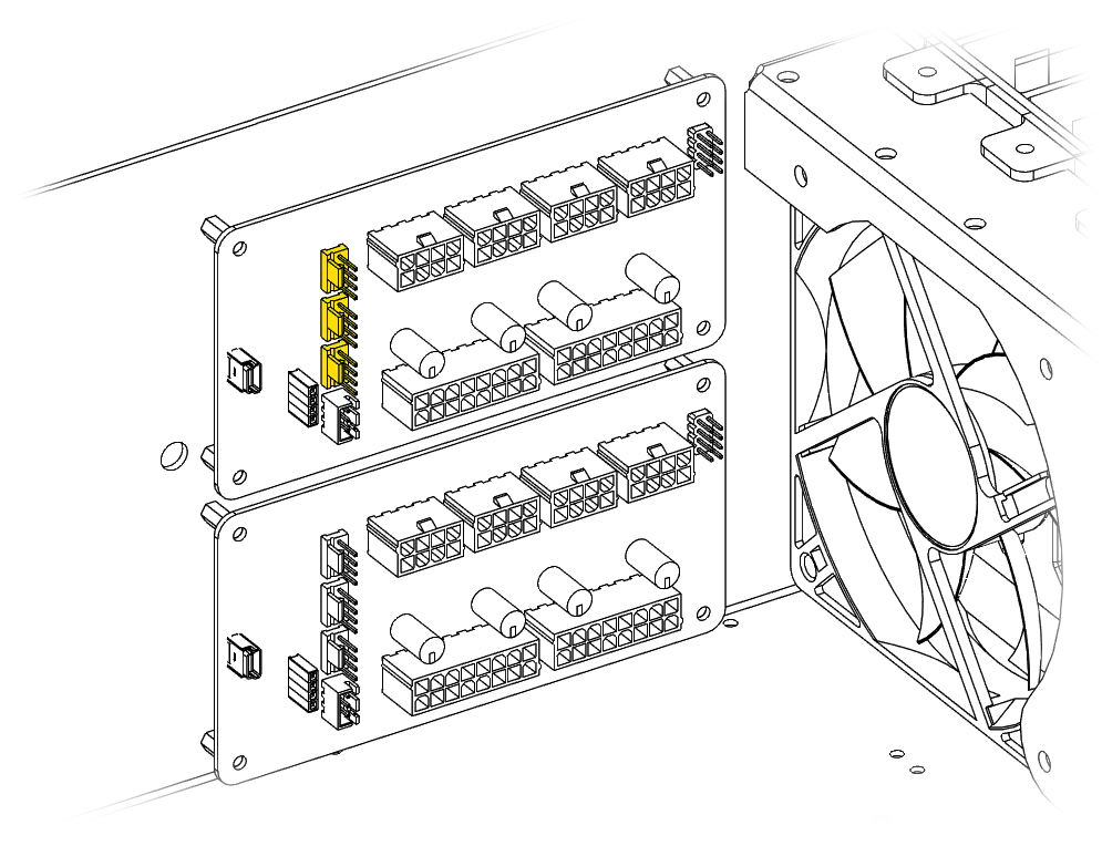 Fan Wall 3 uses the exposed fan headers on the powerboard.
Hako-Core Mini Fan Walls
The Hako-Core Mini does not utilize a third fan wall so the exposed headers can be used for any other fans you may have.
Exhaust Fan
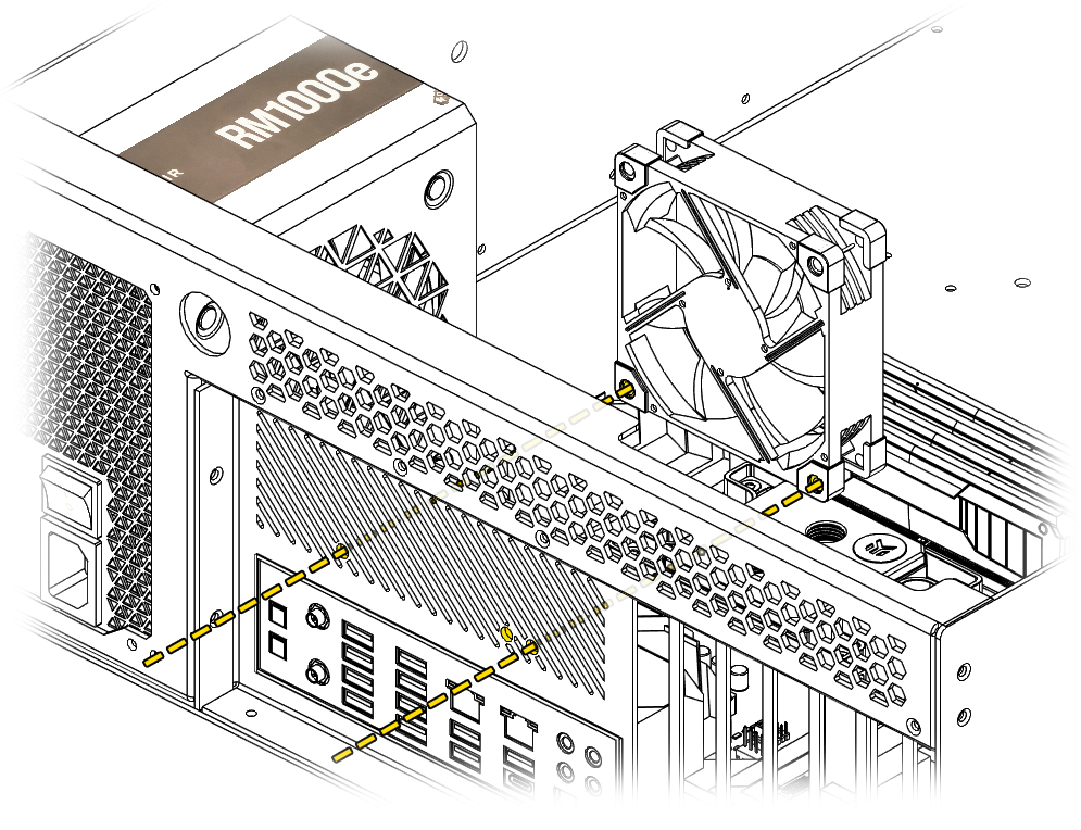 Use the 2 mount points to install a 80 mm or 92 mm fan to help facilitate airflow.
Auxiliary Fans
Auxiliary fans mount to one of two brackets, sold separately.
Angled Fan Bracket
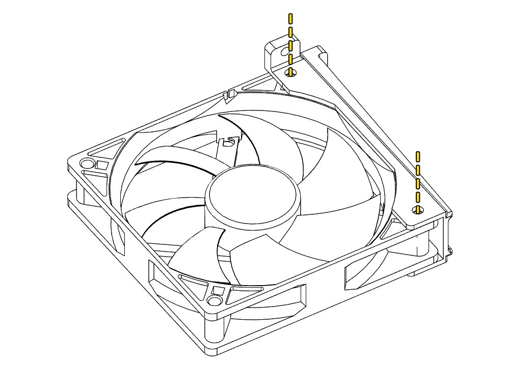 Use 2 of the mounting holes to secure a fan to the angled bracket.
Direction of Air Flow
Take note of the fan mount direction to ensure proper air flow. Depending on the bracket orientation installed in the case, the fan may be flipped.
Angled Overhang Mount
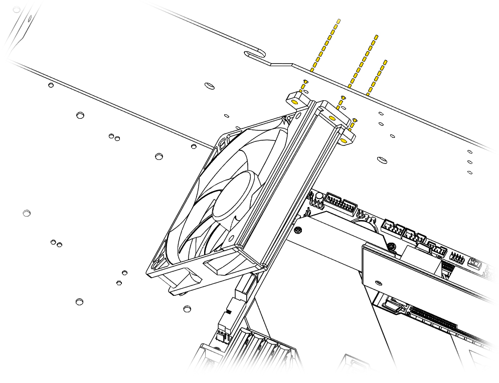
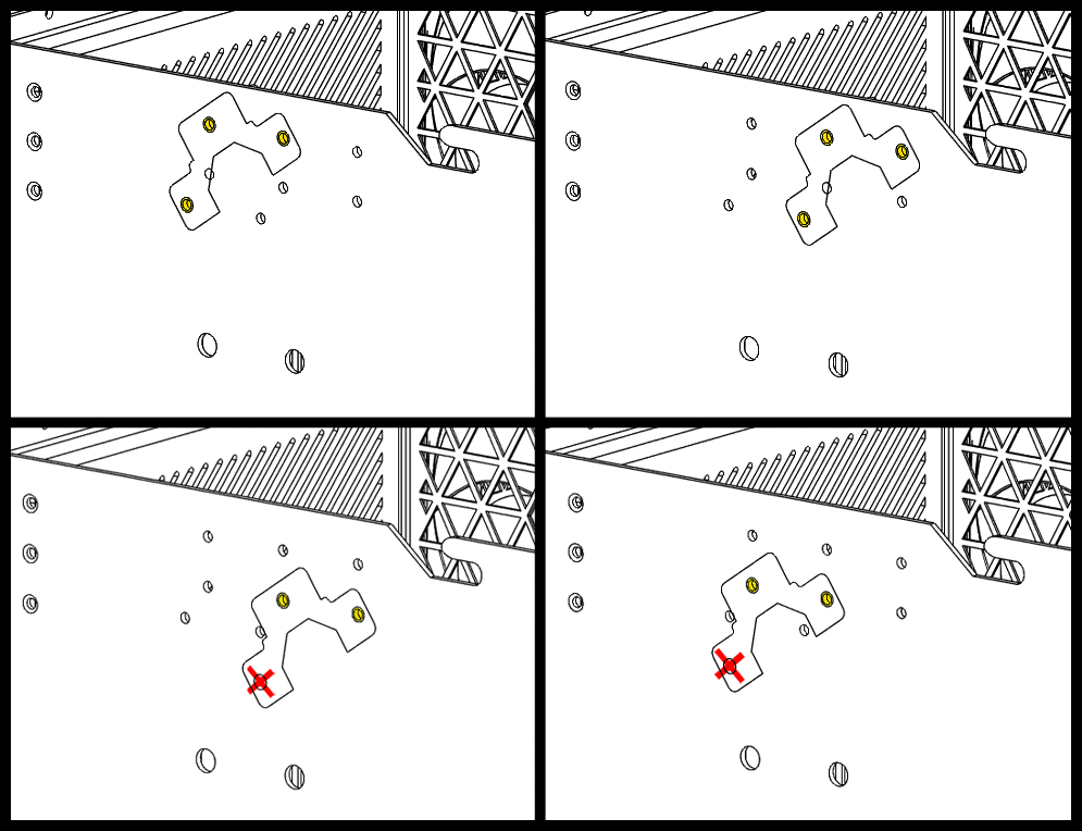 The mounting location can be moved left and right as well as up and down.
Lower Mount Point
When installing in the lowered position, one of the mount points will not be used.
Angled Underhang Mount
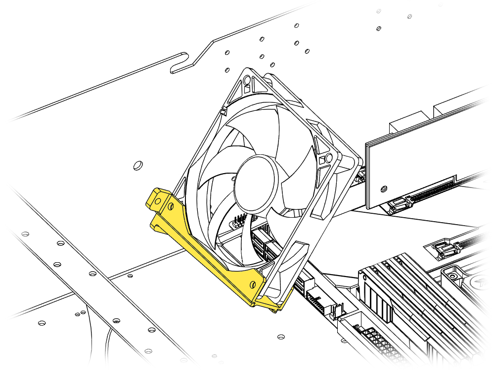
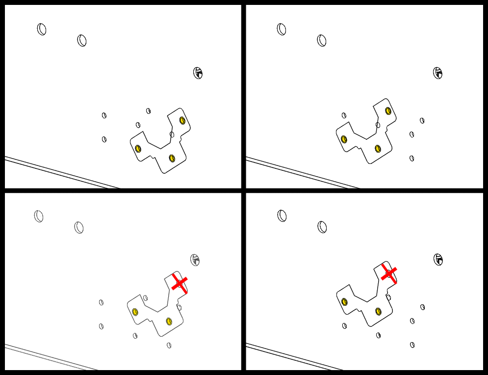 The angled fan bracket can also be under mounted. This can be useful depending on wire clearances with different HBA cards.
Mount Extension
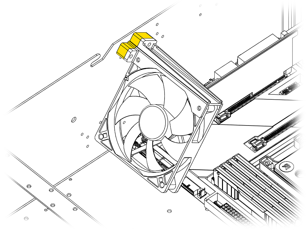 The included mount extensions can be used to extend the bracket out for extra coverage on the furthest PCIe card. Use the extended screws for this configuration.
Horizontal Fan Bracket
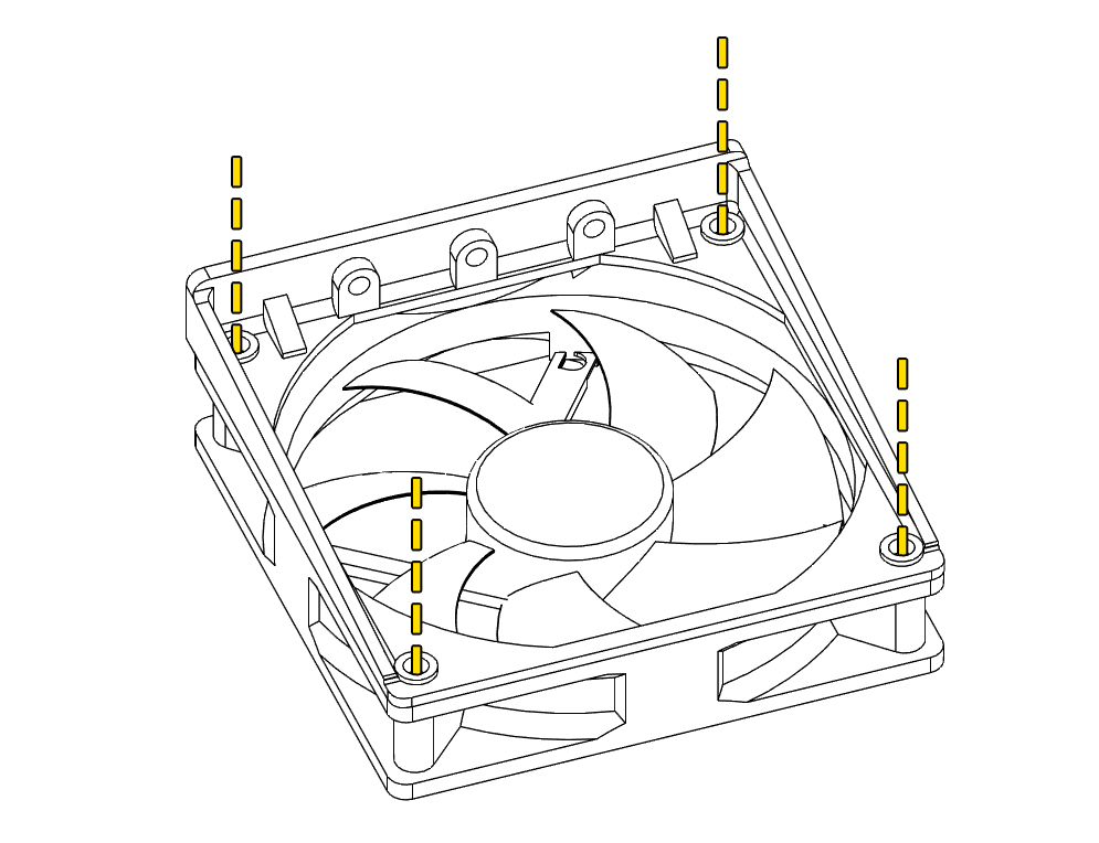 Use 4 of the mounting holes to secure a fan to the horizontal bracket.
Horizontal Overhang Mount
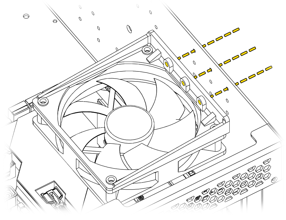
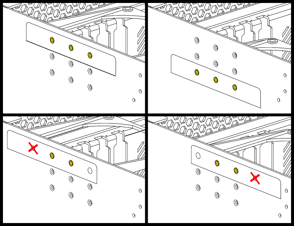 The mounting location can be moved left and right as well as up and down.
Left or Right Mount Points
When installing in the shifted left or right position, one of the mount points will not be used.
Powering Fans
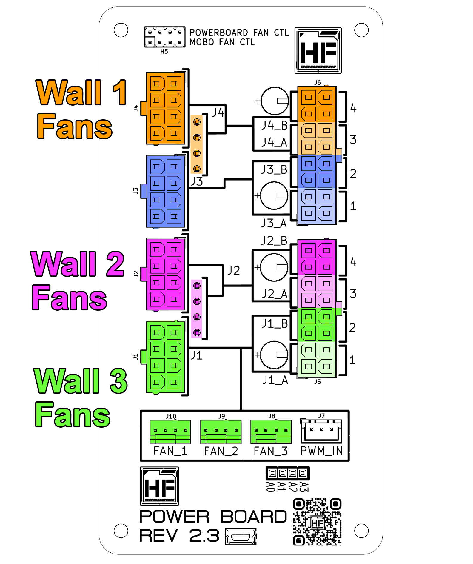
The fans are powered by the 8-pin PCIe connections on the powerboard. Each 8-Pin PCIe connector powers a specific set of hardware. If there is a set of hardware that is not being used in your configuration, connection is optional.
8-Pin PCIe IN 1
- Fan wall 1
8-Pin PCIe IN 3
- Fan wall 2
8-Pin PCIe IN 4
- Fan wall 3
Controlling Fans
Visit the Powerboard Connections page for more information on how the fans are controlled.